Delfoi calibration theory
Learn the idea behind the calibration process
Terminology associated
TCP: Tool Center Point, determines the working point of the robot
Mountplate: The end-plate where robot tools are attached
RMS: Root Mean Square Error, a model that defines positioning accuracy
CAD: Computer Aided Desing, the format of the simulation components
WPP: Abbreviation for Workpiece Positioner
Gantry: A robot positioner with two or three linear axes
LSQ: A calibration method for fixtures and workpieces
6/9pt: A calibration method for fixtures and workpieces
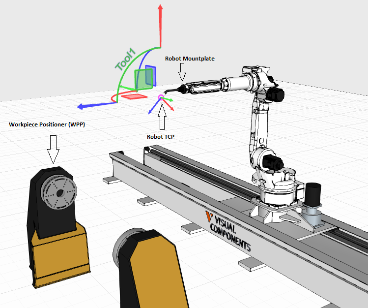
Robot TCP, mountplate and a one-axis workpiece positioner
Principles behind calibration
The idea of the calibration is to match the simulation layout to the real
world as well as possible. This can be achieved with exact measuring
of the robot system. The measurements are conducted with different
spikes, which will determine the TCP for the robot. These spikes are
also used to calibrate the link positions for the external axes. The
use of the spikes also requires that the points are recorded exactly
in correct position.
The measurements are used to align the components in the simulation, which
is why it's important to take accurate measurements. Closed-loop calibration,
where robot is the measuring device, requires high precision from the robot,
meaning, that the TCP RMS needs to be really accurate in order to get reliable
measurements. A rule of thumb for TCP RMS is for it to be below 1, depending
on the application. TCP RMS can be improved by using rigid hardware and taking the
measurement points so, that the mountplate moves as much as possible in all
directions during the measurements.
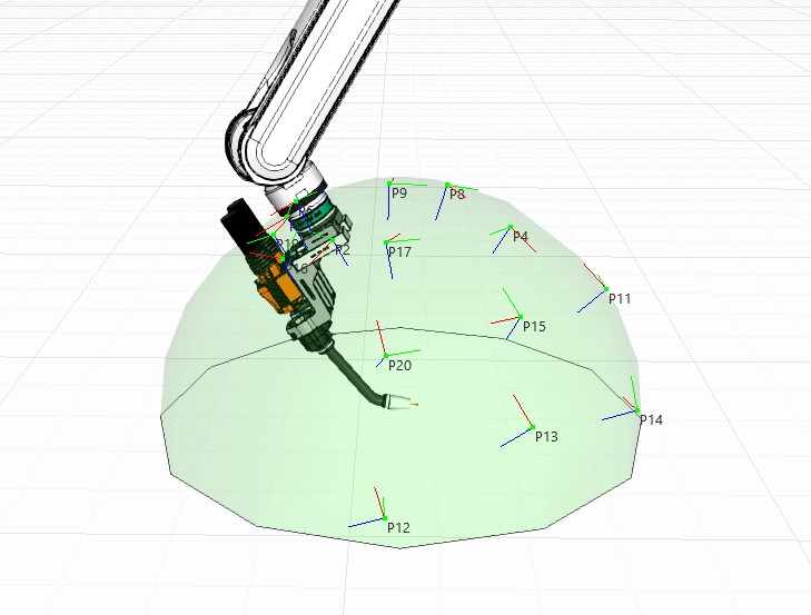
In an ideal situation, the TCP measurement points form a sphere
If the RMS is over 1, the next steps depend on the accuracy demanded by
the application. If the system uses corrective functions, such as searches or seam tracking,
it might not be necessary to fix it in any way. However, if the accuracy is
not acceptable and there are no corrective methods, joint offset calibration
or mechanical robot calibration needs to take place. It is possible for the
robot to be too inaccurate for it to be compensated in any way. A rule of
thumb for the overall precision for the robot system is roughly 1mm for the
robot and additional 1mm per axis involved.
Preparing the calibration
Use precise and well-defined hardware, such as straight and sharp spikes that have not been damaged. When the spikes are attached, make sure that they can not move or wobble while taking the measurements. Also make sure, that the dimensions in the CAD-models match with the real world. If the layout includes heavy fixtures, expect some inaccuracy also from the dynamics of the system.
During calibration measurements
Make sure that the spikes touch exactly when the points are being teached. A piece of paper can be used when touching the spikes to confirm the correct distance between the spikes: When the spikes scratch the paper on both sides and the paper can still be moved in between, the spikes are close enough. When taking the measurements, move only the link you are calibrating and the robot.
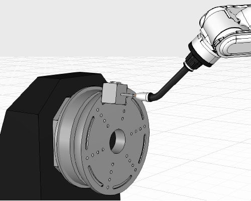
Attach the spike as far away from the rotating center as possible
Record the points as far away from each other for linear movements and for rotational movements set the points as far away from the rotational center as possible.
During software calibration
The calibration order needs to be precisely:
Remember to download the calibration programs with zero tool and touch up the programs to the tool that has the calibrated TCP. After calibrating one component, lock the geometry in Delfoi to minimize the risk of moving anything unintentionally. Create multiple layouts and save often to make sure you have something to come back to if something goes wrong. One layout can only hold one connection from robot to workpiece positioner, so each positioner would need it's own layout.