TCP short spike measurements
Take the following measurements to calibrate the TCP position using the short spike.

TCP short spike
How to take the measurements
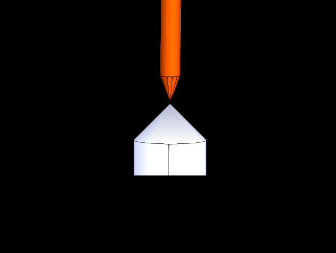
Remember to align the spikes exactly!
Save 8 points
TCP short spike done!
Measurement checklist:
Setting up the measurements
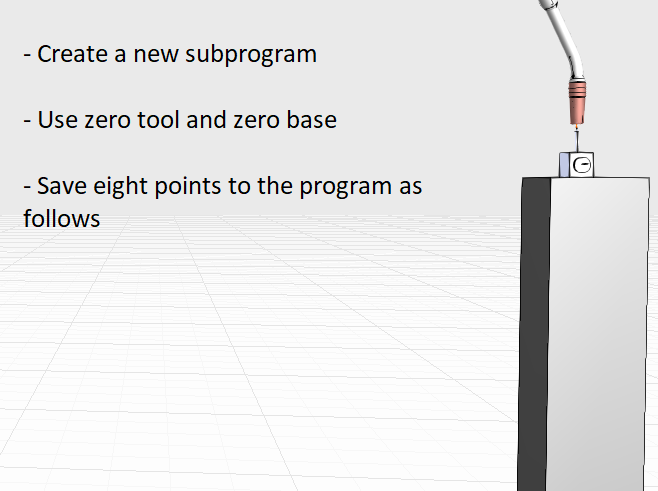
Create a new program in the robot controller and name it so that you remember it, for example shortSpike. Attach the short spike to the robot torch and the spike with the magnet base close to the robot so, that the robot can reach the spike from multiple orientations (see image below). Make sure that the robot is using a zero tool and a zero base.
Spike positioned to a good robot reach
Taking the measurements
Align the spikes so, that the tips match exactly and then save the point to the program using a joint motion type. While taking the points, make sure that the mountplate of the robot covers as big of an area as possible and the robot joints change their values as much as possible between the points. These result in better calibration accuracy. Use a piece of paper to measure the distance between the spikes: When the spikes scratch the paper, the spikes are close enough.
Then change the torch orientation so that the mountplate moves to another position and save a new point with the same tool and base. Then repeat until you have 8 points in your program.
After taking the measurements
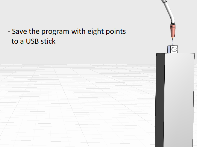
After the measurements you should have one program with 8 points. Save the program in ASCII format to a USB-stick from the controller..
The measurement page usually includes two different info sections
Go through the slides for a compact and mobile friendly experience.
Or go through the more detailed information under button "Click for more information". It is recommended to go through the detailed information before the measurements.