H-frame
How to calibrate an H-frame

Calibration checklist:
Calibrating H-frame positioner
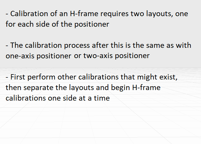
Calibration of an H-frame requires two layouts to be built, so that the calculation for external axes will be correct. So first perform other calibrations and before changing to positioner calibration, save the H-frame sides A and B to their own layouts and proceed with the calibration.
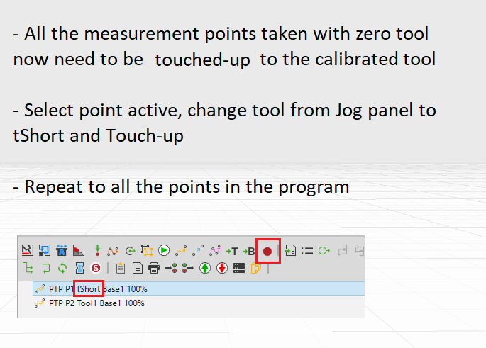
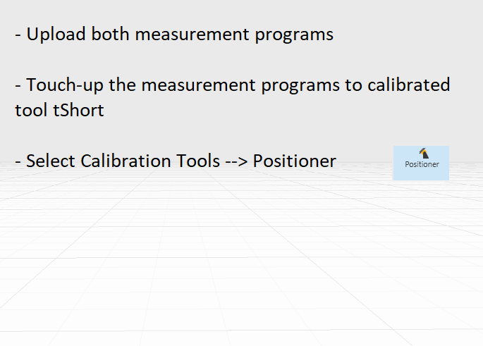
Upload the side A measurement programs to Delfoi, check that the points are in a logical position and that there are no clear measurement or upload errors. All the points need to be then touched-up to the calibrated tool tShort by selecting the Touch-up tool from calibration help tools. Select the scope for current sequence and the tool to the one that has the short spike data and click ChangeTool.
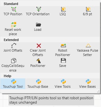
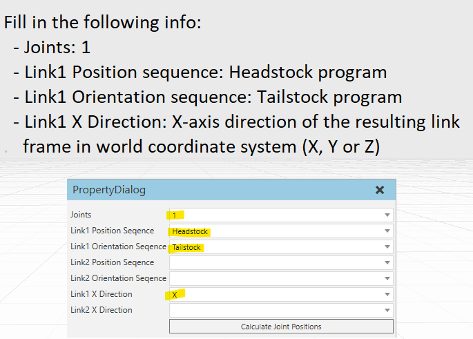
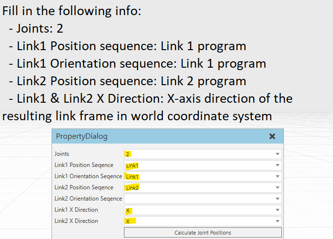
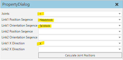
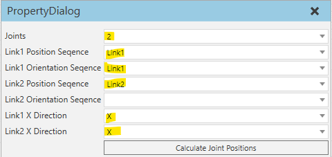
After Touch-up, select Positioner from Calibration Tools. This opens up a dialog, where you need to fill the following info depending on the positioner type on each side of the H-frame.
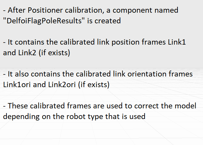
After Positioner calibration, a component name DelfoiFlagPoleResults is created containing the calibrated link positions (Link1 and Link2) and orientations (Link1Ori and Link2Ori). If the link position and orientation seem to be a lot off the simulation model, the model needs to be fixed regarding which robot brand is in use.
After Positioner calibration, a component name DelfoiFlagPoleResults is created containing the calibrated link positions (Link1 and Link2) and orientations (Link1Ori and Link2Ori).
Corrections to the model
If the calibrated link position and orientation seem to be a lot off the simulation model (for example over 4mm, depends on the system and required accuracy), the model needs to be fixed regarding which robot brand is in use.
After finishing with side A, repeat everything to side B.